Footstep Power Generation Project Using Piezoelectric Sensors and Arduino

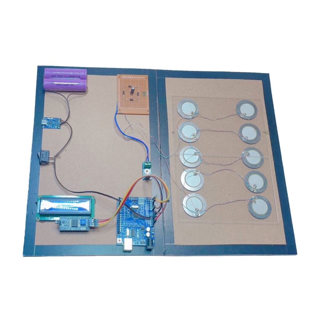
Convert footsteps into electricity! In this project, we build a working model that generates electric power using Piezoelectric Sensors, displays the voltage on an LCD 16×2 with I2C, and stores energy in a Li-ion 18650 battery using a TP4056 charging module. Ideal for engineering students, science exhibitions, and DIY electronics lovers.
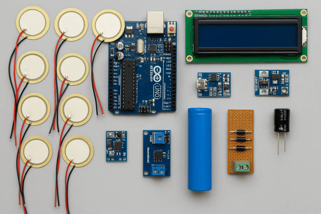
Components Used

• • MDF board base
• • 6 to 10 Piezoelectric Sensors
• • Rectifier circuit (4 diodes + 10µF capacitor)
• • Voltage Sensor Module
• • Arduino Uno
• • LCD 16×2 (with I2C module)
• • TP4056 Li-ion battery charging module
• • 18650 Li-ion battery
• • Push switch
• • Jumper wires, soldered board (5×7 cm)
Circuit Diagram Overview
– ✅ 1. Piezoelectric Sensors to Rectifier
- Connect all 8 piezoelectric sensors in parallel (red wires together, black wires together).
- Connect the combined output of piezo sensors to a full bridge rectifier (made from 4 diodes).
- Piezo output → AC inputs of the bridge rectifier (marked ~ or AC)
- Output of rectifier (+) → Positive terminal of 100µF capacitor
- Output of rectifier (–) → Negative terminal of 100µF capacitor
✅ 2. TP4056 Output to Arduino Power
- TP4056 OUT+ → Arduino VIN
- TP4056 OUT– → Arduino GND
(This powers the Arduino using the battery charged by footsteps.)
✅ 3. Voltage Sensor Module to Arduino
- Voltage Sensor VCC → Arduino 5V
- Voltage Sensor GND → Arduino GND
- Voltage Sensor Signal (S) → Arduino A0
- Voltage sensor input pins connected across the capacitor to monitor voltage generated.
✅ 4. LCD 16×2 with I2C to Arduino
- LCD SDA → Arduino A4
- LCD SCL → Arduino A5
- LCD VCC → Arduino 5V
- LCD GND → Arduino GND
✅ 5. Additional Notes
Use thick wires for rectifier and piezo connections due to high-frequency spikes.
Switch (optional): You may add a switch between TP4056 OUT+ and Arduino VIN for manual power control.
Ensure Capacitor Polarity is Correct: 100µF electrolytic capacitor must have + to rectifier positive and – to rectifier ground.
Arduino Code for Voltage Monitoring and Display (mV)
#include <Wire.h>
#include <LiquidCrystal_I2C.h>
// Initialize LCD 16×2 (I2C Address: 0x27, Columns: 16, Rows: 2)
LiquidCrystal_I2C lcd(0x27, 16, 2);
const int voltageSensorPin = A0; // Voltage sensor connected to A0
float voltage = 0.0;
int milliVoltage = 0;
void setup() {
lcd.init(); // Initialize LCD
lcd.backlight(); // Turn on LCD backlight
lcd.setCursor(0, 0);
lcd.print(“Footstep Power”);
delay(2000); // Display project name for 2 seconds
lcd.clear();
lcd.setCursor(0, 0);
lcd.print(“Voltage: “);
Serial.begin(9600);
}
void loop() {
int sensorValue = analogRead(voltageSensorPin);
// Convert sensor reading to millivolts (Voltage Divider Ratio = 5)
voltage = (sensorValue * 5000.0) / 1023.0; // Convert to mV
milliVoltage = (int) voltage; // Convert to integer for LCD display
// Display voltage on Serial Monitor
Serial.print(“Voltage: “);
Serial.print(milliVoltage);
Serial.println(” mV”);
// Display voltage on LCD in mV
lcd.setCursor(9, 0);
lcd.print(” “); // Clear old value
lcd.setCursor(9, 0);
lcd.print(milliVoltage);
lcd.print(“mV”);
delay(500); // Refresh every 500ms
}
Testing Video
Applications
• • Smart flooring in malls, railway stations
• • Energy harvesting for remote sensors
• • Educational science fair project
• • Concept for green energy research
Conclusion
This project showcases a renewable energy system that harnesses mechanical pressure from footsteps into usable electric power. With a voltage display and battery charging mechanism, it’s both functional and educational.
Tip: You can expand this project by connecting a boost converter and inverter to power a small AC bulb or USB devices.
Available on: Mechanic37.com, Flipkart, Amazon –

Leave a Reply